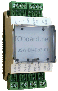
IOboard-Di4Do2 Industrial digital I/O Interface Module 4 inputs 2 outputs

IOboard-Di4Do2 is an interface for 4 digital inputs and 2 digital outputs, supporting a wide variety of industrial devices. Isolation assures high system performance and electrical security.
Housed in a DIN rail mountable case with industrial screw terminals, these modules can be combined with up to 200 other interface modules and, via Ethernet (TCP/IP) or USB Base Modules, to a controlling computer; I/O Modules can also be directly connected to a computer via RS-422, without a Base Module. Using an external 3.3V power supply the number of I/O Modules in the system can be expanded to 200 (addressing limit). The boards in the system are automatically configurable getting addresses during the initialisation.
The digital inputs can be polled or can be set up for events. They are polled using the command GetInput whose response contains all digital inputs. The "0" logic level corresponds to voltage above 9V and the "1" level to a low level below 9V, measured at the input connector. An erroneous connection on the input connector is signalled as a "0" level and signalled by the LED as orange.
Features
| 4 Digital Inputs |
- +24V nominal optoisolated
- Input current: 13mA
- Inputs are floating with an adjustable reference level (0V or 24V)
- Inputs are isolated from the system and from each other (1000Vrms 60s)
- Input states are signalled by LEDs
- An input voltage below +9V (or negative) is signalled as low (LED switched off)
- An input voltage above +9V is signalled as high (LED green)
- A reverse input voltage is allowed (LED orange)
- Max input voltage: +/- 31V
|
| 2 Digital Outputs |
- Each output can be set as a sink or source type
- Max output current: 100mA
- Outputs are guarded by a resettable (PTC) fuse
- Outputs are isolated from the system and from each other (1000Vrms 60sec)
- Output states are signalled by LEDs
- An output voltage below +9V is signalled as low (LED switched off)
- An output voltage above +9V is signalled as high (LED green)
- An overload of output current is signaled by a red LED
- Power supply: 24 V (each output may have a separate power supply)
|
| Connectors |
- Each input has two screw terminals Din+ and Din-
where n = 0...3 (2 LEDs are assigned to each input)
- Each output has four screw terminals Vcn+ (external power supply), Cn (source output), En (sink output) and 0-n (ground)
where n = 0...1 (2 LEDs are assigned to each output)
- RS422 bus: PHOENIX CONTACT COMBICON
|
| Communication: | EtherNet ISO 8802.3 100BASE-T or 10BASE-T with user-configurable IP address. |
| Protocol: | TCP using two channels: Basic, Control. Other protocols can be implemented. |
| Power requirements: | 24V DC (4W) |
| Environment: |
- Operating temperature: 0 to 55°C
- Storage temperature: -10 to 75°C
- Rel. humidity: 10 to 60%
|
| Dimensions: | 53.6mm(W) x 62.2mm(H) x 89.7mm(D) (2.1"W x 2.5"H x 3.5"D) |
| Approvals: | EN 61131-2:2007, CE |
| Warranty: | 3 years parts and labour |
